I wanted to make an upgrade to our ageing Pit Board which was
simply a square piece of carbon fibre with the word ‘In’ written on it in
yellow tape. Given that we race in darker conditions (24hr races and dark
indoor circuits) we needed something that was lit up in some way. We also can
run 3 or 4 different teams in one race so we had to ensure the right kart was
being signalled. After some careful (and some not so careful) consideration a
double digit LED pit board was born. The board is made up of 14 segments with 4
white straw hat LED’s in each segment. Each segment is then switched on or off
using an IRL510 Mosfet (a bit over kill but I had some lying around) mounted on
each segment. The IRL510’s are then controlled by an Arduino (Nano) as the
basic controller for the board. There is an IRF9530 (P Channel) Mosfet on the
positive side to give the PWM and flashing capability.
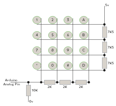
The numbers are selected via a 16 digit keypad on the back
of the board which I converted to use only 1 Arduino pin (see below for the
conversion details).
The front and back are 3mm acrylic sheet with a wooded frame
in between. This was then drilled for each individual LED. The overall size is
the same as an A4 piece of paper.
 |
| Unlit Board |
 |
| All 14 segments wired on stripboard and connected to the Arduino via the 220Ohm resistors |
Power Consideration:
In a 24hr race we would normally do 11 pit stops with an
average of 2 minutes of lit pit board per stop gives 22 minutes per team. We
can run 4 teams so that means the battery life has to exceed 88 minutes (I used
2 hours as the target for safety). Each segment runs 4 Parallel LED’s each
consuming 20mA so each segment uses 80mA. If the number 88 was used then all 14 segments
would be lit and this would consume 1120mA or 1.12A. So we would need a power
source capable of around 1A and at least 2200mAh. At this point the voltage
wasn’t a major consideration as the LED resistors could be adjusted to
compensate providing they were higher than 3.5v when almost empty. I first
looked at Li-ion receiver packs as used in radio controlled cars etc. These
have more than enough power and reasonably priced. However, they also require
specialist chargers which can add considerable cost, especially if you wanted
to charge them from your car or trackside. In the end I decided to use a 5v USB
power bank as I already had 3 basic 2600mAh ones lying around in draws. The
other advantage to using a power bank is they are very easy to re charge almost
anywhere and can easily be swapped. The basic ones will cost less than £5 and
deliver 1A output (not quite enough if 88 is required but you can’t see the LED
de-rating with the naked eye). Given that these are really 3.7v li-ion
batteries which are converted to 5v there is some loss in the conversion so the
2600mAh rating is probably more like 2000mAh at 5v, but this should give 2
hours of run time before re charging.
 |
| Rear showing the key pad and the 5v power bank |
Making the 16 digit keypad work with 1 Arduino pin:
Converting an 8 pin, 16 digit keypad to use 1 Arduino pin is
relatively simple and there are many versions available via google. Essentially
we will make each row and each column have a different resistance creating a
unique voltage for each key and as a result any of the analog pins on the
Arduino can read this voltage and work out which key was pressed.
 |
| Resistor used to convert key pad to use a single pin |
Functionality:
Power on via the rear mounted power switch will bring the
device on and a zero will be displayed on the board (this is to show the user
its on and ready but also its to draw power on the power bank, Typically power
banks require at least 50mA draw to stay switched on). The first key press will
then move the zero to the left digit and display the number on the right digit.
The second key press will the move the right digit to the left position and add
the new number to the right digit. The 3rd press will reset the
board and return a zero to the left digit and the new number to the right
digit.
i.e. 1st press = 5 then the board will display
‘05’.
2nd press = 7 then the board will display ‘57’.
3rd press
= 8 then the board will show ‘08’
There are also some other functions available, pressing the
* key will toggle the flash function on or off. Press the ‘A’ key and the board
will display ‘FL’, this could be used for fastest lap or a reminder to fuel the
kart (which is what we use it for). Pressing the ‘B’ key will display a ‘P’ on the left digit, follow this
with a number press and the display can then show race position. And finally
the ‘C’ and ‘D’ keys will increase or reduce the display brightness.
The sketch is quite basic (it could probably be more basic). It starts by checking if a flashing function is set or not and then
takes the appropriate action. After that it just loops waiting for a key press
to occur. Once a key press occurs it then reads the voltage from the analog pin
and then through a series of ‘IF’ statements works out which key was pressed. Once
the key has been worked out it then takes the appropriate action.
Arduino Sketch available soon


No comments:
Post a Comment